The Polyline button allows to draw a polyline passing through the specified points.
Quick Access Panel: ![]()
Ribbon: Editor -> Draw -> Polyline
Menu: Draw -> Polyline
A polyline can consist from line segments and circular arcs. All these segments are a single object. To every segment of the polyline width can be attributed separately. The button is in the Editor tab under the section Draw. In the classical menu the command is under the Draw menu.

Polylines can be closed, i.e. two segments come from each vertex. Only polylines with two or more segments (3 or more vertexes) can be closed. One can close a polyline both at the moment of creation and after finishing to draw it. To close a polyline at the moment of its creation select the command Close in the context menu. The tool Rectangular allows to create a closed rectangular polyline.
To add a polyline
1. Click on the button ![]() .
.
2. Click to set the first point or enter the coordinates via the dynamic input.
3. Drag the pointer to draw a straight line.
4. Click once at each position where you want a new segment to appear or enter new segment's coordinates on the keyboard. By default a line segment is drawn.
5. Right click and select Arc from the context menu to add a circular arc.
6. Drag the pointer and specify the diameter of the arc.
7. Right click and select Line from the context menu to add a line segment.
8. Use Ctrl+Z to undo the last drawn part of a polyline
9. Double-click when done.
Note: Editing the segments is available after the creation of the polyline.
The command Fillet enables the user to create a circular arc to the created linear segment and the conditional linear segment that is perpendicular to the created one. The command is available from the context menu at the stage of polyline creation. Fillet cannot be created in the following cases:
•after a circular arc, as well as after the one created with the command Fillet;
•for creation of the first polyline segment.
Radius of the fillet is "0,5' on default. It can be changed in the window of dynamic input after selection of the command.
Editing the Polyline
To edit a polyline use the markers which appear after having selected the object in the drawing. Line segments have the markers of the beginning, the end and the centre. Markers of the centre for circular arcs which help to set the direction of the convexity and the height of the chord. Linear segments markers of the centre enables the user to relocate the polyline segment parallel to the current position. Markers are moved with the left mouse button: point the cursor at a marker, after the marker changes its color into yellow, after that it can be moved with the left mouse button pressed.
Different width for the segments of a polyline is set with the help of the properties Global Width, Start Segment Width and End Segment Width. In contrast to the property Lineweight, these parameters set the width of a polyline the display of which depends on the performed zoom.
A polyline has a set of properties which can be viewed and edited in the Properties panel:
Property |
Description |
|---|---|
Color |
Defines the color of the polyline |
Layer |
Defines the layer which the polyline belongs to. The property contains a list of all available in the drawing layers and allows to move the polyline to another layer. |
Line Weight |
Defines the lineweight of the polyline. Is selected from the standard values. You can turn the function of showing the lines according to their lineweight on or off. Each lineweight value corresponds to a number of pixels on the screen. The number of these pixels isn't changed while scaling in the program window. The scale of lineweighht display on the screen is set in the Visualization tab of the Options window. |
Linetype |
Defines the linetype of the polyline. Is selected from the standard values. |
Linetype scale |
Sets the scale for the current linetype. By default it is 1. |
Vertexes |
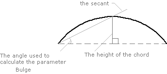
Contains a group of parameters which are aet for everu vertex separately: •Count. The total amount of vertexes of the polyline. Vertexes are the beginning and the end of a segment. If they meet at one point, then it is one vertex. •Index. Switches between the vertexes of a polyline to edit the segments. Switching is performed with the help of the arrows which appear after activation of the field. The active vertex in the drawing is marked with yellow, and all the rest - with blue. •X, Y. The coordinates of the current vertex in the XY plane. •Bulge. The value of the tangent of the angle which is formed by a secant passing through the point of the intersection of the circular arc and the height. It takes the values from 0 to 1. If the arc is drawn clockwise fron the starting to the end point, this value is negative. 0 means it is a line segment, 1 means it is a semicircle.  •Bulge height. The value of the height of the circular arc. •Start segment width. Sets the start segment width. •End segment width. Sets the end segment width. |
Global Width |
Sets the common for all the segments width which depends on the performed zoom. |
Length |
Sets the common for all the segments length. |
Area |
The area defined by the polyline. |
Go to ABViewer